About
BeyondCAD provide Software Development, Customisation, Automation and Implementation services to the Computer Aided Design industry. We specialise in developing solutions for 3D CAD and Data Management Systems such as SolidWorks, but we can help out with a wide range of tools from the latest 3D systems to older 2D products.
Over the years we have seen countless companies and individuals waste precious time and money repeating the same jobs time and time again so a lot of our work in the past has involved programming CAD systems to automate tasks. This can be achieved with off the shelf products such as DriveWorks, for which we are certified to train and use, or a more bespoke solution. Most CAD systems have an application programming interface (API) which allows them to communicate with other programs. Using a CAD system’s API can be an extremely cost-effective way of improving the design process. For example, it's possible to automate repetitive tasks such as batch-printing, searching for documents, generating reports, or to completely automate the design of families of products using rules.
With a combined experience of over 25 years in the CAD industry working closely with CAD resellers and the software developers themselves we are ideally placed to assist you with you needs. We've got lots of contacts in the CAD industry, so even if we can't help you directly, we'll probably know somebody that can.
Services

Application Development
We've got years of experience developing applications of all sizes, from simple utilities to full commercial applications. We will work closely with you to create an application to match your exact specifications.

Design Automation
Using a CAD system’s API can be an extremely cost-effective way of improving the design process. We can write an automation process from scratch for you and we are also very experienced using the DriveWorks suite of products.

ECAD translation
Tim was one of the original developers of the highly successful CircuitWorks so we are well placed to help with translation between ECAD and MCAD applications.

Data Management
We have many years experience with data management products, and understand the varying needs these systems need to address. We have experience of many PDM systems and their interfaces to CAD, including SmarTeam, Agile and SolidWorks PDM.

Solid/Surface Modelling
As an Elite Application engineer, Stephen has years of experience of modelling using SolidWorks and is very comfortable with solid, surface and multibody modelling. We can convert existing 2D data to full 3D models and offer advice to improve your current practices.

Training
As a certified instructor with more than ten years experience teaching the full range of SolidWorks modelling courses as well as Driveworks, we can ensure you get fully up to speed with bespoke training courses that suite your needs.

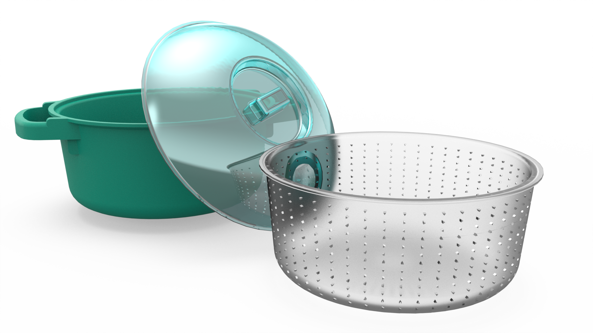
Rendering
Using your models, we can create fantastic high resolution images of your products in a range of formats to use in websites and marketing materials.

Animation
Animations showing off how good your product looks, or how to assemble and service it can be created from your existing CAD data.

Technical Communication
We can create technical images for use in documentation or websites as well as animations showing how to assembly or service your products.
Who we are

Stephen
An Elite SolidWorks Application Engineer with a degree in Aerospace Technology who worked at one of the most highly regarded SolidWorks resellers for almost 11 years. During this time he became the Support Manager and the expert in several areas, especially their technical communication software SolidWorks Composer, even writing the training manual now used throughout the reseller group he was part of.
Stephen has a wide range of skills and experiences including training, consultancy and demonstrations of the SolidWorks suite of products. He has been involved with implementing PDM systems and complex DriveWorks automation for large companies as well as creating marketing content such as webinars, hands on events, renders and animations.
Tim
After graduating with a degree in Mechanical Engineering in 1998, Tim entered the CAD and PDM arena where he worked for two large CAD Resellers developing solutions primarily for the SolidWorks marketplace. Tim then helped develop CircuitWorks, the first SolidWorks Partner Product to attain SolidWorks Gold Partner status in the UK, before its purchase by Dassault Systèmes.
Tim has been involved in many large enterprise projects that have required heavy customization of both CAD and PDM products. He’s also spent time working freelance and developing solutions as diverse as automated stair lift design tools to website creation, to delivering API Training courses. Tim was employed as a Senior Software Developer at Dassault SolidWorks before creating ecad.io, an online electrical translation package which was ultimately acquired by Autodesk where he became a Senior Architect.


Projects
-
CircuitWorks Bi Directional ECAD-MCAD
Translator
The Problem
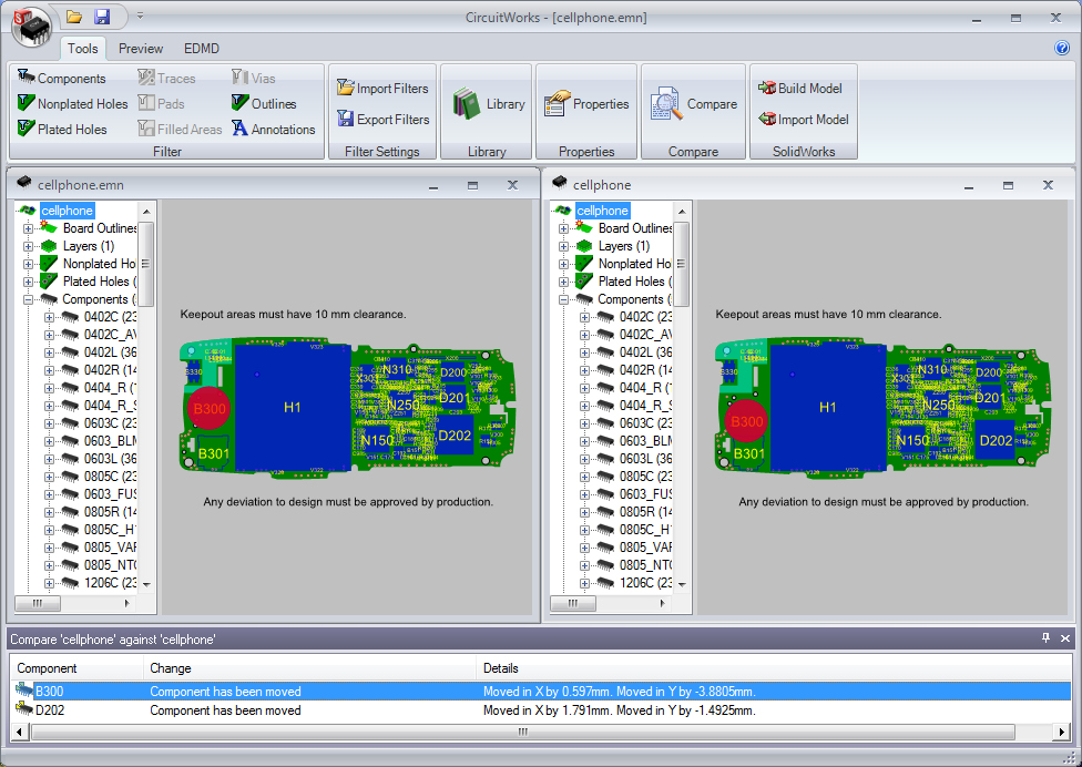
CircuitWorks was initially developed as a response to a request from a SolidWorks Reseller in the late 1990’s. Their prospect was keen to purchase SolidWorks CAD, but at the time it had no ability to read files from Electrical CAD (ECAD) Systems used to design Printed Circuit Boards (PCBs), which was available in some of SolidWorks’ rival products. The initial brief was for a product to read the industry-standard IDF file format produced by ECAD systems and generate a 3D model of a PCB and its components in SolidWorksOur Solution
The first version of CircuitWorks was successfully developed for that single customer, but was soon turned into a SolidWorks Partner Product and sold throughout the SolidWorks channel. Further functionality was added to CircuitWorks over the years: It became bi-directional, with the ability to export SolidWorks models to ECAD systems. Properties, viewing and filtering tools were added to the product, along with support for more ECAD file formats such as Mentor PADS *.asc and ProSTEP EDMD. Over the course of the next ten years CircuitWorks developed into a major SolidWorks Gold Partner Product with more than a thousand customers worldwide - including some of the world's major electronics and defence companies. In 2007 a version of CircuitWorks was developed for the SpaceClaim 3D CAD system. Shortly after, in 2008, the product was purchased by SolidWorks. CircuitWorks is now included as part of SolidWorks Premium.Technologies Used
CircuitWorks was initially written in Visual Basic, but was later rewritten to take advantage of the newer Microsoft .net framework in VB.net and C#. It communicates with SolidWorks using the SolidWorks Application Programming Interface (API) -
ECAD.IO online ECAD/MCAD Translator
The Problem
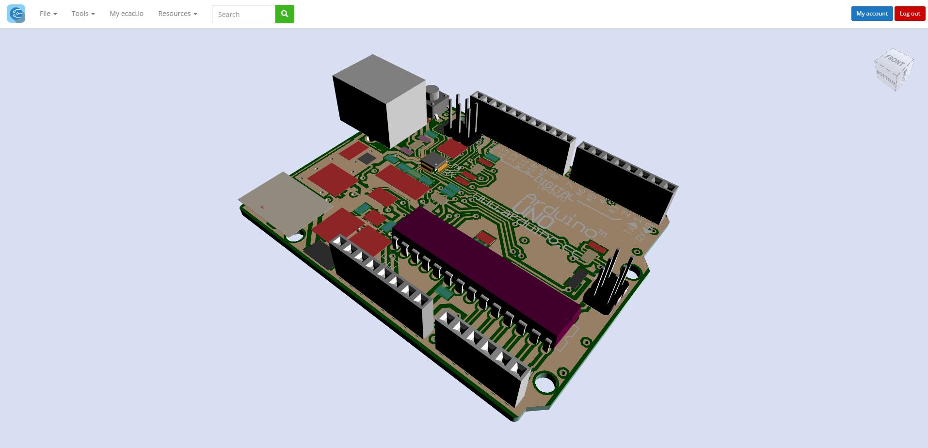
ECAD.IO was developed to bring ECAD/MCAD conversion to the web so that it could be used in any CAD system, anywhere. Also the inclusion of an online library that could be shared amongst the users/community was required to create a seamless conversion tool for all.Our Solution
ECAD.IO is an online ECAD/MCAD conversion tool with library. This uses HTML5/ WebGL to bring a full 3d interface to allow easy PCB conversion online and was co-created by Tim then later sold to Autodesk Ltd who were very interested in its capabilities. Tim then continued to develop the product as an employee for Autodesk and it is indeed still in use today.Technologies Used
- Microsoft MVC/ASP.NET
- HTML5
- Three.js
- C++/MVC/ASP.NET
-
SolidWorks Enterprise PDM Addins
The Problem
SolidWorks Enterprise PDM has grown massively since it was released in 2007 and has become the standard for data management of SolidWorks files. However, for a total data management solution, it is necessary to integrate with not just SolidWorks but with a whole host of Windows applications that might require their files managing too. Enterprise PDM provides some ‘Add-Ins’ out of the box, which essentially provide an easy way of accessing PDM functionality directly from its application (Check-In/Check-Out/Revision History etc.). Microsoft Office products are supported as well as some other CAD systems, but for anything that isn’t supported it becomes necessary to create an add-in for a total data management solution. Two such products that required an add-in were CoCreate ME10 and Zuken E3 Series.Our Solution
Our solution was to create a user interface that directly interacted with these systems to enable easy Check-In/Check-Out functionality, revision control, populated drawing borders and provided search facilities all from within the application. This required a full understanding of Enterprise PDM and its API, an understanding of how the files in these products are used, as well as a knowledge of their respective APIs. The add-in for Zuken e3 was created for a large e3 reseller, and was eventually sold to Zuken for use as part of their larger ‘E3 WireWorks' product. The add-in for ME10 was created for a large SolidWorks reseller and is used in many sites throughout EuropeTechnologies Used
- Zuken E3
- CoCreate ME10
- SolidWorks Enterprise PDM
- Microsoft Visual Basic.Net
-
SmarTeam to Enterprise PDM Migration Wizard
The Problem
Over the years, there have been many data management products used in the CAD industry. Older products are superseded by new products which are often incompatible with the products they've replaced. It can be be very complex to migrate CAD data from an one data management system to another. No two solutions are the same - they often have different work-flows and methodologies, and use different technologies to manage their data. When Enterprise PDM was released for SolidWorks it offered many advantages over previous SolidWorks data management systems, so many customers wished to migrate to the new system. SmarTeam was one of the early PDM products customers often wished to replace, so, working with a SolidWorks reseller, we developed a tool to make the data migration process as smooth and as trouble-free as possible.Our Solution
We created a wizard to guide the customer through the process of migrating their data from SmarTeam to Enterprise PDM. The wizard was designed to be highly configurable, as no two customer's PDM installations are the same. The wizard enabled the user to control the level of migration required - either to migrate one project at a time, or to perform a complete data migration. The wizard could also allow the user to choose to migrate all their files or just those of a certain type. It also gave the user the options to automatically generate folders and to determine how to map the fields from SmarTeam to the fields in Enterprise PDM. This tool was invaluable for the reseller in migrating their customers to the new system and gave them a major advantage over their competitors. They even licensed the product to other SolidWorks resellers in other territories to aid them in their data management migration projects.Technologies Used
- SmarTeam PDM
- Enterprise PDM
- SolidWorks Document API
- SQL Server Stored Procedures and Database Scripts
- Microsoft Visual Basic.Net
-
Automated stairlift design using AutoCAD
The Problem
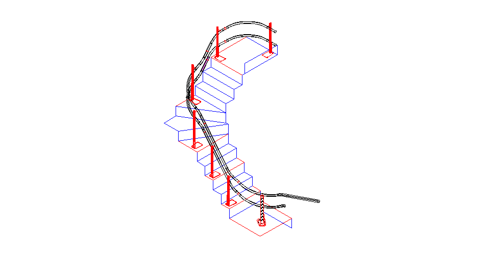
Inertia was asked to develop a solution for a leading stairlift manufacturer to help automate the design of their stairlift rails. What looks at first glance like a fairly simple problem has a number of complex factors, especially for curved staircases or those with many flights. For example, the rail that supports the chair needs to follow the basic profile of the staircase. However it can't come too close to the stairs (or the chair may collide), or rise too far above the stairs (causing the user to collide with the ceiling).Our Solution
Inertia’s solution was developed in partnership with the client to help automate the design of the most efficient rail profiles possible considering both the design constraints of the rail and the manufacturing process, using a 3D model of the customer’s staircase as a basis for its calculations. As well as the design constraints of the staircase to consider, there are also the constraints of the manufacturing process. For extruded designs only certain angles of curve can be manufactured, and there are even more restrictions for designs made from standard components.Technologies Used
The solution was developed with AutoCAD using the AutoLISP programming language. -
Automated tooling design for the packaging
industry using SolidWorks
The Problem
Another common use of CAD API is to use rules to automate the design of ’Change Parts’ for machinery. In the packaging industry for example, Change Parts will be fitted to a machine to allow it to manufacture a particular size of carton. If the producer wants to make a different size of carton then the Change Parts are swapped over for a set designed to produce cartons of that size. Our customers had manual processes for creating these Change Parts using sets of ‘out-of-scale’ 2D drawings. The value of each dimension of each component was calculated manually by the Engineer from an equation and then added to the drawing. This solution has a number of disadvantages – it’s extremely time consuming, and very prone to errors. As the drawings created are not to scale, it’s also virtually impossible to see if a mistake has been made.Our Solution
As the design of Change Parts is dependent on the size of the carton, by specifying the dimensions of the carton, the CAD system can be programmed to automatically generate the models, drawings and manufacturing data to create the components required. Inertia has developed solutions for several packaging machinery manufacturers to automate the design of machine Change Parts with SolidWorks. Rather than applying complex equations to individual parts, our solutions work by using rules within the CAD models as much as possible to generate full 3D models of the finished assemblies and their associated drawings. Producing correctly sized models virtually eliminates the risk of errors, and also enables the 3D models to be used directly for manufacturing, either by CNC machining or increasingly using 3D Printing. As well as saving time and reducing mistakes, automating the design of Change Parts frees up designers for more complex design work. By producing a simple, easy to use interface to drive a complex CAD model, non-skilled users can generate complex CAD models and drawings knowing they'll be correct and within the size range that machine supports.Technologies Used
- SolidWorks API
- Visual Basic.net
-
Multi-cad viewing and batch printing
The Problem
Our customer had their engineering drawings in many different formats: They had migrated from paper drawings to 2D CAD, then from 2D CAD to 3D CAD. They’d also acquired other companies over the years, all using different CAD systems. They had legacy drawings saved as AutoCAD, Cadra, SolidWorks, PDF and even TIFF files. Different drawings were stored in different locations according to their source system and type; some were under the control of PDM and some were simply saved on a file server. The company wanted a simple, easy to use program which could enable non-technical staff to quickly locate, view, and print any drawing or set of drawings, irrespective of the CAD system it was originally created in.Our Solution
We designed a simple single window program for the client, based on a third-party CAD Viewer control. When the user types a drawing number into the program, the code analyses the drawing number, retrieves the drawing from the correct location and displays it on screen without a need for CAD software to be installed. The user can check the drawing is correct, take simple measurements and print it if required. The program is particularly useful on the shop floor where its simple, consistent interface easily allows non-CAD trained staff to retrieve a drawing without the need to go to the Drawing or Production Offices. The same program was later enhanced for the client to allow batch printing of drawings from a report generated from their ERP system. When a particular machine is issued for production by the ERP system, a report is automatically generated which can be read by the Batch Printing/Viewing Program to produce a list of drawings that are printed out automatically.Technologies Used
The program was written in Visual Basic.net using Spicer and AutoVue Viewer controls. -
PDM/ERP Part Numbering Tools
The Problem
Any data management system will provide a number of tools to help manage the life cycle of a product, including revision control, BOM creation (both for drawing office and for manufacturing), part number creation and advanced search capabilities. These tools are very flexible and highly configurable, but often they’re not powerful enough and there is a need to create bespoke tools. In order to enable this, most PDM and ERP Systems provide an Application Programming Interface (API) to allow for more powerful customisation.Our Solution
We have created many different tools to enhance the capabilities of document management systems including: Part Numbering: A flexible XML-configurable part numbering tool to allow for the use of multi-level categorised part numbers such as the Brisch numbering system, and securely storing them into a SQL server database. This was automatically initiated on creation of a SolidWorks part and the file was saved with this number as its file name. PDM to ERP tool: An advanced XML-configurable tool to automatically bring data into any SQL server based ERP system. This would require some configuration and knowledge of the database structure of the ERP system, but when in place brought all the relevant information into the ERP system when the document was released in Enterprise PDM.Technologies Used
- SolidWorks Enterprise PDM
- Microsoft SQL Server
- Microsoft Visual Basic.NET
Contact
If you’d like to know more about our services, don't hesitate to get in touch
Please fill out this form and we'll get back to you within 24 hours